How to Program an ESP8266 ESP-01 with an Arduino Nano
July 3, 2019
The ESP8266 ESP-01 board is a tiny little board with a microcontroller that also includes a wifi network interface. It is also very cheap, you can find one online for about 1€. If you have a project that needs wifi connectivity, but not too many pins, it’s perfect.
Here is the pinout of the board:
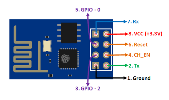
You should be careful that it needs a 3.3V power source to operate. Powering it with 5V will probably fry it. Similarly, you should not send a 5V signal to the RX pin when programming it, or any other pin for that matter.
The easiest way to program it is probably using a dedicated USB programmer, that you can also find very cheap online, for less than 1€. But since I didn’t have one, I decided to program my ESP-01 using an Arduino Nano board as a USB interface to it.
In order to program the ESP-01, you need to connect the Nano and the ESP-01 according to the following picture:
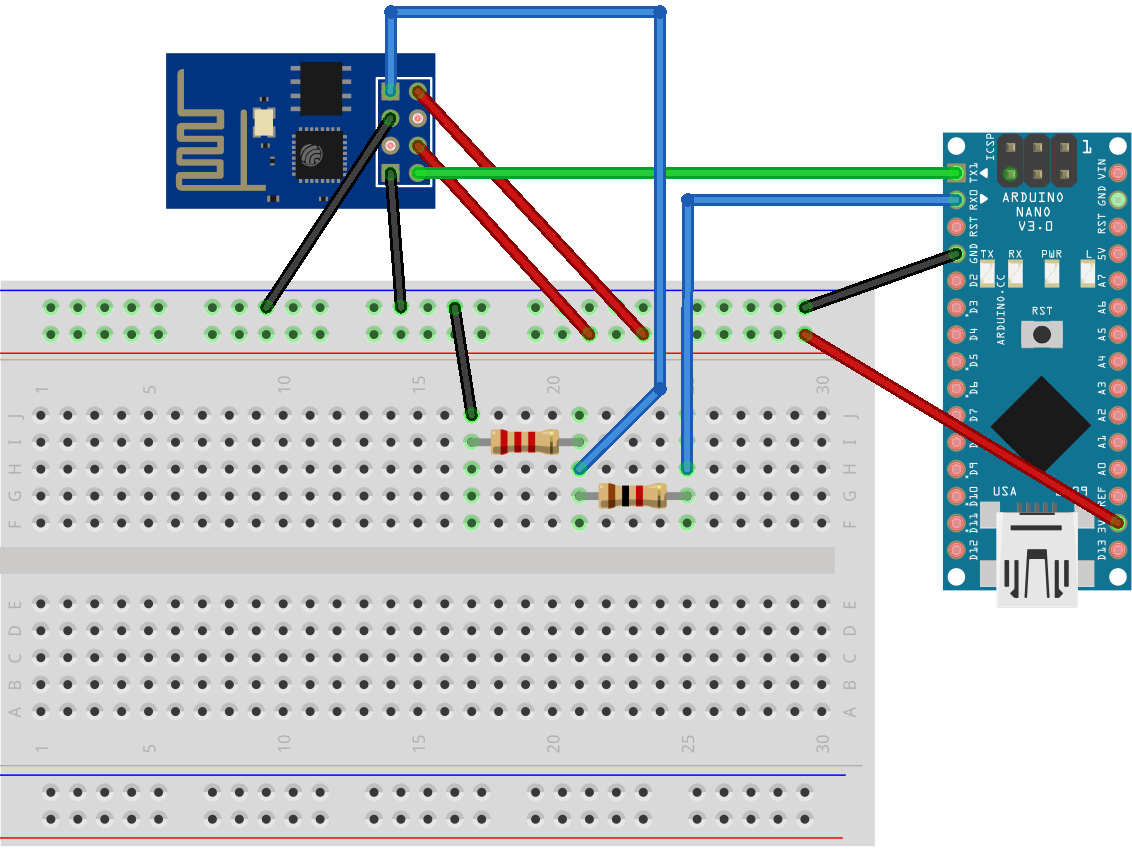
Notice that I have added a voltage divider to the connection that leads to the ESP-01 RX pin. That is because the Arduino outputs 5V from its own RX pin. I used a 1kΩ (first one, on the lower right) and a 1.8kΩ (second one, on the upper left) resistors, so that would bring the 5V output down to about 3.2V according to my calculations, which is close enough to the 3.3V that ESP8266 needs.
To program it using the Arduino IDE, choose “Generic ESP8266 module” as your board from the menu. Now, also connect the Nano’s RST pin to GND. This is important. Connect the Nano to your PC’s USB port. Here comes the hard part: hit the upload button. Once the two lines of white text that inform you that the sketch has been compiled show up, disconnect the RST pin from GND. The timing here is very tricky and you need to be very patient. I get it right about 1⁄10 times, which sucks. If it works, you should be able to see the progress in the Arduino IDE and also see the ESP-01’s led flash. If it doesn’t, you’ll get an error like the following:
warning: espcomm_sync failed
error: espcomm_open failed
error: espcomm_upload_mem failed
error: espcomm_upload_mem failed
in which case, you should connect the RST to GND again, and start over. Rinse and repeat until it works.
Once you’re done programming the ESP-01, remove the GND connection from the GPIO0 pin. If you need to monitor the serial console, swap the TX and RX pins. Otherwise you can remove them completely too. Also remove the connection from CH_EN pin, you only need the VCC and GND pins connected for the ESP-01 to operate. That’s it, your ESP8266 should be working now and if you added code to connect it to your wifi network, you should be able to see it.